聯(lián)系我們
- 上海耐創(chuàng)測試技術(shù)有限公司
- 聯(lián)系人:陳工
- 電話:021-39197548
- 郵箱:zhujing@forcechina.com?
- 地址:上海市嘉定區(qū)馬陸鎮(zhèn)寶安公路2999弄東方慧谷50號2層

基于矩陣補(bǔ)償方法的串?dāng)_修正
文章出處:未知人氣:發(fā)表時間:2017-07-26 13:30:18
CROSS-TALK COMPENSATION USING MATRIX METHODS
基于矩陣補(bǔ)償方法的串?dāng)_修正
David Schrand, SDI Inc.
美國SDI公司 David Schrand
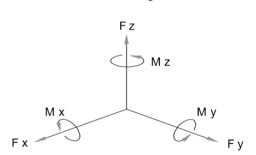
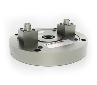
力/力矩傳感器設(shè)計用于【沿著定義的軸向,通常標(biāo)記為X,Y和Z】測量力和力矩。這些力/力矩傳感器由1~6個通道;6通道的力/力矩傳感器包含三個通道的力Fx,Fy,Fz和三個通道的力矩Mx,My,Mz;
理想狀態(tài)是,一個測量軸上的負(fù)載將不會在其它任何測量通道上產(chǎn)生輸出。
現(xiàn)實是,沒有任何多軸向傳感器可以做到這種互不干擾;
對于大多數(shù)的多通道傳感器而言,這種不需要的輸出,我們稱之為串?dāng)_,一般在1%~5%之間;雖然1%~5%的串?dāng)_聽起來不多,但是對于有六個通道的力/力矩傳感器而言,每一個通道都會有來自其它五個通道的串?dāng)_,這種串?dāng)_疊加在一起就可能造成5%~25%的串?dāng)_輸出;
There are basically two methods used to reduce this potential source of measurement error. With the first method, the load-cell is ‘tuned’, either mechanically or electrically to reduce the channels output due to off-axis or extraneous loads. While effective, this method is time consuming and is not practical if more than two extraneous loads need to be compensated for. The other method of cross-talk compensation involves mathematically manipulating the load-cells output data to correct the cross-talk outputs. It is effective for any number of extraneous loads, and can be characterized as mathematical cross-talk compensation by the application of “cross coupling coefficients”, or the inverse matrix method. This is the method that will be discussed here.
基本上,有兩種辦法來減少由多通道之間的串?dāng)_帶來的測量誤差:
第一種方法是在傳感器后端加補(bǔ)償電路和對傳感器機(jī)械結(jié)構(gòu)進(jìn)行改良,以求達(dá)到減小【非測量軸的外來負(fù)載引起的通道輸出】;這種方法雖然有效,但是如果要補(bǔ)償兩個通道以上的外部負(fù)載,這種方法是耗時且不切實際的;
第二種是通過數(shù)學(xué)方法,對各個軸向的負(fù)載輸出進(jìn)行解析校準(zhǔn)來得出正確的通道輸出值,這種方法對于任何數(shù)量的外部載荷都是有效的,并且可以通過應(yīng)用“交叉耦合系數(shù)”或逆矩陣方法來表征為數(shù)學(xué)串?dāng)_補(bǔ)償。
我們將要講的就是矩陣系數(shù)方法。
When a load is applied to a force sensor, the measurement channel that lines up with that load will respond. However, as described earlier, other measurement channels that are not in line with that applied load will also respond to that load. That’s the bad news. The good news is that that response is repeatable for any given load or combination of loads. This means that by carefully applying these extraneous loads during the calibration process, and recording each channels output response to those loads, an output profile of the sensor can be created. From here, a series of simultaneous equations can be created to describe the cross talk performance of the force sensor. By solving this series of equations using any set of simultaneous data from all the channels of the sensor, the true loading condition that produced that unique set of data can be determined. The drawback to this method is that a sensor channel is required for each extraneous load that is present during loading. This usually isn’t a problem, since in most instances, a measurement channel is present to monitor all the significant loads present in the application
當(dāng)負(fù)載施加到力傳感器時,與該負(fù)載對應(yīng)的測量通道將響應(yīng)輸出。然而,如前所述,與施加的負(fù)載軸向不一致的其他測量通道也將對該負(fù)載做出響應(yīng)。這是壞消息,好消息是,對于任何給定的負(fù)載或負(fù)載組合,該響應(yīng)是可重復(fù)的。這意味著通過在校準(zhǔn)過程中仔細(xì)地應(yīng)用這些無關(guān)的負(fù)載,并記錄每個通道輸出響應(yīng)到這些負(fù)載,可以創(chuàng)建傳感器的輸出輪廓。
從這里,可以創(chuàng)建一系列聯(lián)立方程來描述力傳感器的串?dāng)_性能。通過使用來自傳感器的所有通道的任何一組同時數(shù)據(jù)來求解該系列方程,可以確定產(chǎn)生該唯一數(shù)據(jù)集的真實負(fù)載條件。該方法的缺點在于,需要加載標(biāo)定傳感器的所有軸向。這通常不是問題,因為在大多數(shù)情況下,我們可以在加載的同時用數(shù)據(jù)采集設(shè)備監(jiān)測每一個通道的輸出。
OFx = K1 ·Fx
At the same time, the output from the other five channels will be recorded as cross talk outputs. Now the transfer functions for the sensor begin to take shape.
同時,其他五個通道的輸出將被記錄為串?dāng)_輸出。現(xiàn)在傳感器的傳遞功能開始形成。
OFx = K1·Fx
OFy = K7·Fx
OFz = K13·Fx
OMx = K19·Fx
OMy = K25·Fx
OMz = K31·Fx
From this set of equations, the transfer functions (K1, K7, etc), can be determined for each axis by dividing the sensors output by the applied load.
通過這一組方程,可以通過將傳感器輸出除以施加的負(fù)載來確定每個軸的傳遞函數(shù)(K1,K7等)。
This same procedure will be used to calibrate the remaining five axes of the sensor, providing the remaining transfer functions. Using the theory of superposition, they can be combined to yield the output equations that fully describe the output of the sensor to all the applied loads
將使用相同的過程來校準(zhǔn)傳感器的剩余五個軸,提供剩余的傳遞函數(shù)。 使用疊加理論,可以組合產(chǎn)生完全描述傳感器對所有施加載荷的輸出的輸出方程。
OFx = K1·Fx + K2·Fy + K3·Fz + K4·Mx + K5·My + K6·Mz
OFy = K7·Fx + K8·Fy + K9·Fz + K10·Mx + K11·My + K12·Mz
OFz = K13·Fx + K14·Fy + K15·Fz + K16·Mx + K17·My + K18·Mz
OMx = K19·Fx + K20·Fy + K21·Fz + K22·Mx + K23·My + K24·Mz
OMy = K25·Fx + K26·Fy + K27·Fz + K28·Mx + K29·My + K30·Mz
OMz = K31·Fx + K32·Fy + K33·Fz + K34·Mx + K35·My + K36·Mz
These equations describe the output of the sensor in terms of the applied loads. However, in application, the loads are the unknowns, and the outputs are the known measured quantities. With these six equations and their six unknowns (the loads Fx-z and Mx-z), it will be possible to solve for the unknown loads.
這些方程式描述了傳感器在施加的載荷方面的輸出。 然而,在應(yīng)用中,負(fù)載是未知數(shù),輸出是已知的測量量。 利用這六個方程及其六個未知數(shù)(載荷Fx-z和Mx-z),可以解決未知載荷;
【逆矩陣方法】
The series of equations described above can be solved by using what is called the inverse matrix method. A brief overview of the theory behind this technique is given in Appendix A, ‘Inverse Matrix Theory’. In essence, it is a technique that ‘inverts’ the equations so that instead of having the output as a function of the loads as described above, the loads are now functions of the outputs.
Finding the inverse matrix used to correct or compensate a sensors output due to cross talk errors, involves gathering calibration data on the sensors response to extraneous loads, and using it to construct a matrix that can be used to find the sensors true loading condition. A multi-axis sensor that has undergone a thorough calibration, will already have such a cross talk matrix supplied with the calibration data. More information on the steps involved in creating this matrix is presented in Appendix B, ‘Finding the Inverse Matrix’.
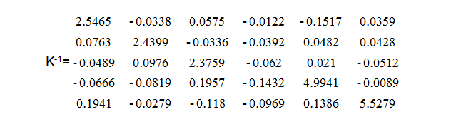
This may all seem confusing, but it is a very simple way to handle a very complex problem. For example, we have a sensor that is ‘less than perfect’. We do however have the cross talk matrix that was supplied with the sensor, as listed below.
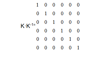
可以通過使用所謂的逆矩陣法來解決上述的一系列方程式。反矩陣?yán)碚摚覀兛梢詤⒖季€性代數(shù)中的逆矩陣求法來取得【K·K-1=E】。實質(zhì)上,這是一種“反轉(zhuǎn)”方程式的技術(shù),使得不再像上述那樣將輸出作為負(fù)載的函數(shù),所以負(fù)載現(xiàn)在是輸出的功能。
用于糾正或補(bǔ)償由于串?dāng)_錯誤導(dǎo)致的傳感器輸出的逆矩陣涉及到收集傳感器上的校準(zhǔn)數(shù)據(jù)對外部負(fù)載的響應(yīng),并使用它構(gòu)建可用于找到傳感器真實負(fù)載條件的矩陣。已經(jīng)經(jīng)過徹底校準(zhǔn)的多軸傳感器將已經(jīng)具有提供校準(zhǔn)數(shù)據(jù)的這種串?dāng)_矩陣。有關(guān)創(chuàng)建此矩陣涉及的步驟的更多信息,請參見附錄B“查找逆矩陣”。
這可能看起來很混亂,但是處理一個非常復(fù)雜的問題是一個非常簡單的方法。例如,我們有一個“不太完美”的傳感器。然而,我們確實提供了傳感器提供的串?dāng)_矩陣,如下所示。
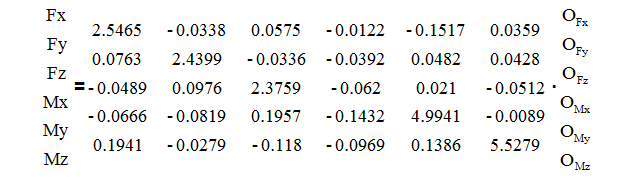
With this inverse matrix the loads that produced any set of simultaneous data from the sensor can be calculated. We start with the inverse matrix, K-1, and the equation:
X = K-1·O
使用該逆矩陣,可以計算產(chǎn)生來自傳感器的任何一組同時數(shù)據(jù)的負(fù)載。 我們從逆矩陣K-1和方程式開始:
X = K-1·O
Or, in long hand:
或者展開寫:
At a particular point in time, we obtain the following readings from our sensor:
OFx = -1.6510 mV/V OMx = 1.0054 mV/V
OFy = 0.6151 mV/V OMy = 0.8402 mV/V
OFz = 0.2501 mV/V OMz = 0.0067 mV/V
在特定的時間,我們從傳感器獲取以上數(shù)據(jù)
To find the Fx load that must have been present to create those six outputs, we multiply the elements of the first row of the inverse matrix by the individual outputs that were recorded, and sum them:
要找到必須存在的Fx負(fù)載來創(chuàng)建這六個輸出,我們將逆矩陣的第一行的元素乘以所記錄的各個輸出,并將它們相加:
Fx = (2.5465 * -1.6510) + (-0.0338 * 0.6151) + … + (0.0359 * 0.0067) = -4.35 lb
Similarly, the remaining five loads can be calculated by carrying out the same operations on the remaining five rows of the inverse matrix. Doing so yields the following loading conditions:
類似的,可以通過對逆矩陣的剩余五行執(zhí)行相同的操作來計算剩余的五個負(fù)載,這樣就能得出一個完整傳感器的加載概況;
Fx = -4.35 lb Mx = 5.54 in lb
Fy = 1.37 lb My = 4.11 in lb
Fz = 0.69 lb Mz = -0.31 in lb
In actual use, these calculations can be set up to be done in real time by the data acquisition or control system, or can be done by post processing the data after the test is complete by using a spread sheet program. This technique will typically reduce the cross talk to less that 0.5% of the full scale capacities of the sensor.
在實際使用中,這些計算可以通過數(shù)據(jù)采集或控制系統(tǒng)實時設(shè)置,也可以通過使用電子表格程序在測試完成后對數(shù)據(jù)進(jìn)行后處理來完成。 這種技術(shù)通常會將串?dāng)_減少到傳感器滿量程的0.5%。
知識點回顧:K·K-1=E
以上就是六維力傳感器矩陣系數(shù)標(biāo)定的過程,僅供參考,如有錯誤請指正!


 滬公網(wǎng)安備 31011402003414號